
Last Edit: Sunday, March 21st, 2021
Table of Contents
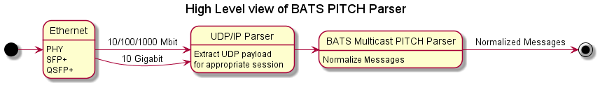
High Level View
In today’s post, I will go over how I used LabVIEW FPGA, along with the LabVIEW FPGA IP Export Utility to generate a netlist that parses and normalized BATS Multicast PITCH Market Data messages.
You can use this netlist on non-NI hardware, as long as I export the netlist for the appropriate Xilinx Family/Series.
This assumes that you already are using an FPGA “Smart-NIC”, sometimes known as a FPGA Accelerated Network Card that has a valid BATS Multicast PITCH feed. This is a Proof-of-Concept where you can connect a UDP payload to this IP and get a normalized version of each Market Data message that can be used for building an Order Book in the FPGA in the style of your choosing.
References
- LabVIEW FPGA (on ni.com)
- LabVIEW FPGA IP Export Utility
- https://github.com/fpganow/arty_bats
- BATS Multicast PITCH Specification
My Hardware and Software
I am using a cheap Arty A100T ($250 USD) development board along with LabVIEW FPGA 2020 (non-SP1 version)
Interface
Like all FPGA IP, the inputs and outputs are based on connecting wires to input and output signals. On each clock cycle, you usually wire an ‘input valid’ signal along with several signals indicating the values, while on the output side, you read the same – a signal indicating that the output is valid along with a few more signals for the respective values. This is a very simple interface, as opposed to a FIFO where a packet of data is sent with 1 or more elements. In summary – one input per clock cycle, and one output per clock cycle.
Input
The input to the IP is an AXI-like interface that is suitable for both LabVIEW FPGA and Verilog/VHDL designs:
- Data (u8) – A single byte of data. With some modifications, this can be converted to an array of 8 bytes, or a 64-bit unsigned integer, which is what 10 Gigabit data comes in as. (If you know enough LabVIEW FPGA, you will understand the distinction between a 64-bit unsigned integer and a fixed-size array of 8 bytes)
- Data_Valid (Boolean) – Just a signal that indicates whether data is valid for the current clock cycle.
- Reset (Boolean) – Resets the internal state of the IP. Takes 1 clock cycle for the IP to reset.
- Ready_for_Udp_Input (Boolean) – Specifies that the IP is ready for new data.
Data Types

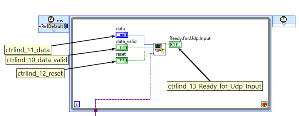
LabVIEW
If you are using this IP from a LabVIEW design, you would have to wire in the following 4 signals:
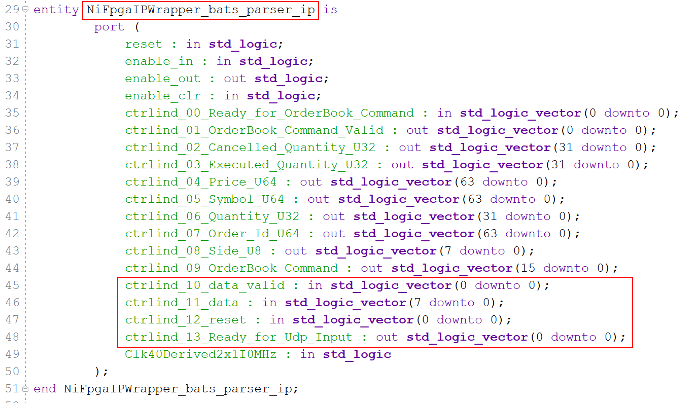
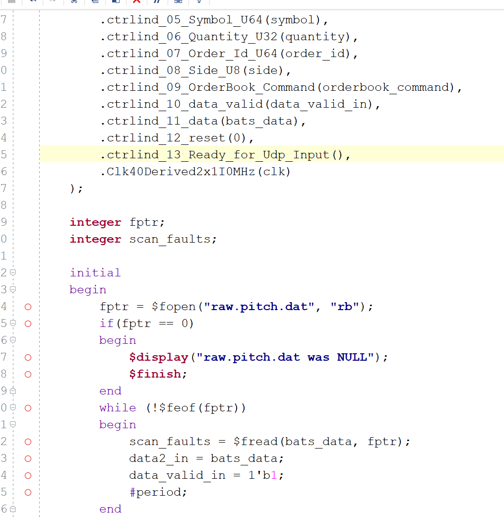
VHDL
If you are using this IP from Vivado, you will have to import the following VHDL ‘entity’. I have highlighted the entity name and the input signals.
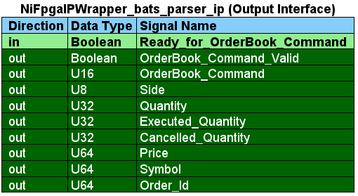
Output
The output interface follows the same paradigm as the input interface and has all of the elements of an OrderBook command available in 1 clock cycle.
- Ready_for_OrderBook_Command – Tells the IP that is going to be reading the output signals that it is ready to receive a new OrderBook Command.
- OrderBook_Command_Valid – Indicates whether a valid OrderBook command is present.
- OrderBook_Command – This is the actual Command, which is the integer value of the LabVIEW Enum variable type.
- Side – The ASCII value of the side (Buy – 0x42, Sell – 0x53)
- Quantity – Number of shares
- Executed_Quantity – Number of executed shares
- Cancelled_Quantity – Number of cancelled shares
- Price – Price
- Symbol – Symbol represented as right-justified ASCII padded on the right with spaces
- Order_Id – Order Id.
Data Types
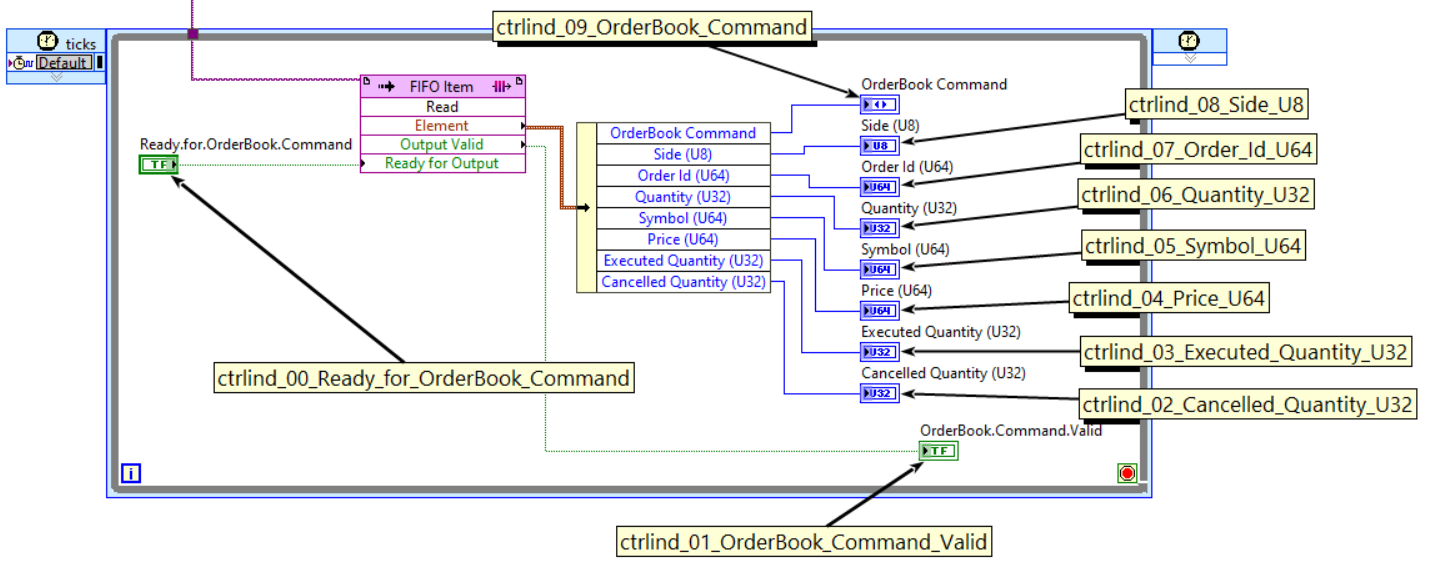
LabVIEW
I have placed a comment box for each output-interface signal that corresponds to the name which is generated by the IP Export Utlity.
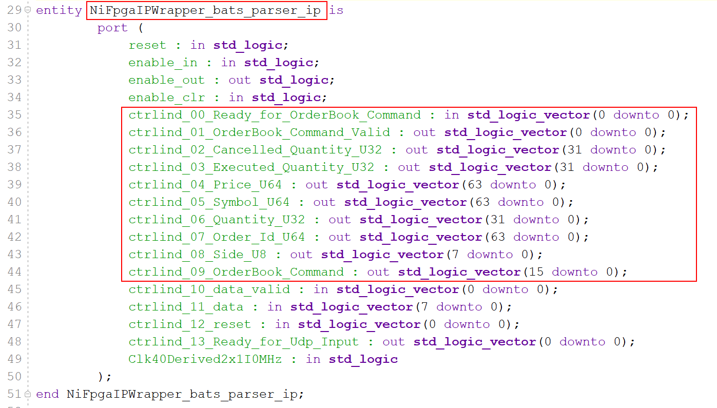
VHDL
In order to import this IP in to your existing Vivado project, you will have to import the following entity using VHDL or Verilog. I have highlighted the output signals. (Note: by ‘output’ signal, I mean signals related to getting the output from the IP, and not signals with a direction of ‘output’)
Top-Level Implementation
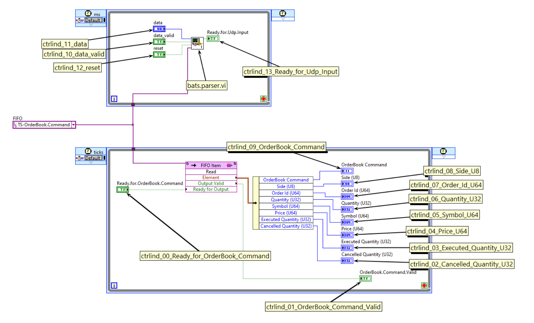
So when looking at this IP in LabVIEW, you have to open the ‘bats.parser.ip.vi’ VI and this is what you see. The 2 large boxes are single-cycle timed loops, and the wires connecting them are a VI-Scoped FIFO. A lot of the implementation details that would normally exist in a Vivado implementation have been abstracted by LabVIEW, and what you see below is the equivalent of at least 50 VHDL files.
State Machine
Everything inside the small box labeled ‘bats.parser.vi’ from the screenshot above can be represented by the following state machine:

LabVIEW State Machine
The “Read Add Order” State from the state machine diagram above is represented in LabVIEW code with the following below:
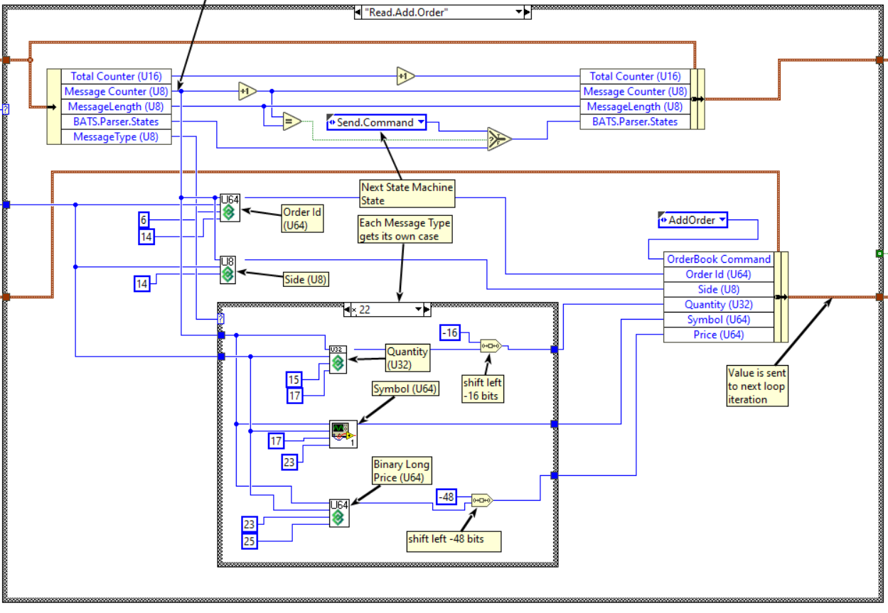
Close up for Add Order States
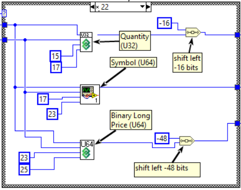
In the “LabVIEW State Machine” diagram above, there is a box or Case-Structure inside the outer Case-Structure which has the MessageType wire plugged in to the Case Selector input. If the message type is ADD ORDER Long, it will execute the following code which parses the Quantity starting at index 15 and ending at index 19.

If the Message Type is 0x22, the same variable – Quantity – will be read starting at index 15 and ending at index 17. The Quantity only takes up 16 bits in the specification, but since we are normalizing each message format, we are storing it in a 32-bit number.
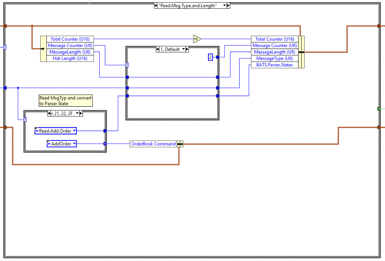
Read Message Type and Length State
There are 3 wires coming in to this Case Structure, the top wire is a cluster – which is similar to a structure in C – contains all the values to be read in on each iteration, and to the right – the corresponding output values.
On each loop iteration – or clock cycle – we read the input values, make some changes such as store the Message Type and modify the output values. As an example, on the first clock cycle, the ‘Message Counter (U8)’ variable (or wire) has a value of 0, the Case Selector runs the loop for ‘0’, which causes it to store the length in the Message Length variable (or wire), then the Message Counter variable is incremented by one and the loop runs again.
Simulation with Vivado Simulator
You can take the netlist – NiFpgaAG_bats_parser_ip.vhd – and run a Vivado Testbench around it:
- https://github.com/fpganow/arty_bats/blob/main/vivado/src/ip/NiFpgaAG_bats_parser_ip.vhd
- https://github.com/fpganow/arty_bats/blob/main/vivado/src/hdl/test/bats_parser_tb.v
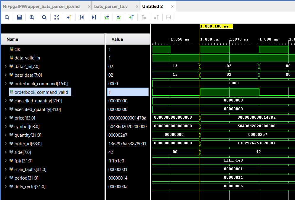
On my computer, I run it for 1 microsecond and I get my first ‘orderbook_command_valid’ result. The test data is also included in the github repository. The test data is actually based on something I found in an old repository on github (https://github.com/klon/bats-pitch-parser)
Notice how the orderbook_command_valid value is true for only one clock cycle, and during that cycle all the values for an entire OrderBook command are also set. (I did not reset them to 0 after that, but this is a Proof-of-Concept…)
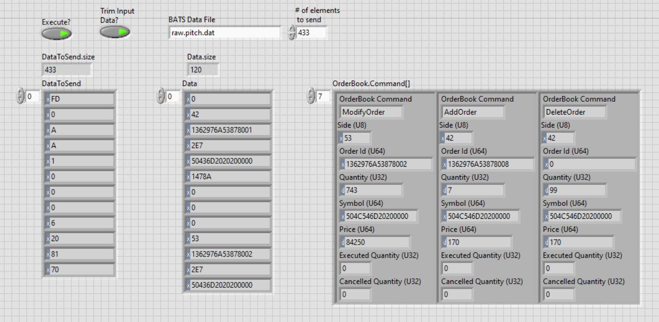
Simulation with LabVIEW Simulator
Now running simulation from LabVIEW FPGA is a bit different. You are still writing an application using LabVIEW, but you start on the host, read a data file and pump the data in to the FPGA over a FIFO in much the same way that the FPGA would receive data from another source, which in our case would be a FIFO that replaces the Ethernet stream and UDP/IP Parser.
I clean things up by taking the results – which are the OrderBook Commands and display them in a easy-to-read processed format.
Instructions for Running
Clone the source code repository,from Vivado source the arty_bats.tcl script:
|
git clone git@github.com/FpgaNow/arty_bats cd {x:/arty_bats/vivado} source ./arty_bats.tcl |