
Skip directly to the source code on Github.com here:
https://github.com/JohnStratoudakis/LabVIEW_Fpga/tree/master/MarketData/MarketData_01
So what now. We know what a NASDAQ ITCH 4.1 Market Data Message looks like. The format is very simple, there is some – yes – ASCII data in the message format, and all messages are preceded by the message length. Message length preceding the message makes it very easy to interpret a feed from inside an FPGA.
What to do first? Well, what does eXtreme Programming say to do? It says keep it simple.
So, I am working on a LabVIEW 2016 program that does the following:
- Open a NASDAQ ITCH file
- Send it one byte at a time into the FPGA over the PCIe bus
- FPGA reads the feed, skips over messages types that it does not know how to handle, and parses only messages of a specific type.
- Send back to the host computer a statistic – any statistic for now.
If you are unfamiliar with National Instruments products and LabVIEW, go here to learn more:
Step 1 – Open a NASDAQ ITCH file
The first step is to create a LabVIEW for Windows – as opposed to LabVIEW for FPGA – and to read in an entire NASDAQ ITCH 4.1 file. This file is quite big, so I wrote a quick Python script (used Ryan Day’s code as a guide: https://github.com/rday/ITCH41), and I generated a file with the following:
- 1 Timestamp message
- 5 Timestamp messages
- 50 Timestamp messages
The Python script can also output the seconds field from each message read in. See the python script here:
https://github.com/JohnStratoudakis/LabVIEW_Fpga/blob/master/MarketData/MarketData_01/parseItch.py
Now I have three files, named: T.itch, T.5.itch, and T.50.itch, and I will write a LabVIEW program to send all data from one of the files above in to the FPGA.
Step 2 – Send Data From One File to FPGA via DMA FIFO
This requires knowledge of LabVIEW for Windows and some knowledge of LabVIEW for FPGA. I wrote a simple User Interface that allows you to select a file. That file is then sent to the FPGA using a Host-to-Target FIFO 1 byte at a time. Since viewing a LabVIEW vi requires that you have LabVIEW installed on your computer, I took some screen shots of the LabVIEW code and placed them here:
- https://github.com/JohnStratoudakis/LabVIEW_Fpga/blob/master/MarketData/MarketData_01/Host-Send-Data.png
- https://github.com/JohnStratoudakis/LabVIEW_Fpga/blob/master/MarketData/MarketData_01/Host-Top-Level_1.png
Step 3 – Interpret the Feed Inside the FPGA
Right now I have generated a file that contains, 1, 5, and 50 Timestamp messages. So that means, for each messaged that is encountered, I will extract the timestamp, which will be in seconds, save it in to a local FPGA variable, and send the value back up to the host.
Step 4 – Send Data Back to Host
The statistic will be the seconds portion of each message that was passed in. The seconds field is a 32-bit integer, so the Target-to-Host DMA FIFO will be a 32-bit integer. Here is a quick screen shot of the FPGA top-level loop, which reads the input data stream one byte at a time:
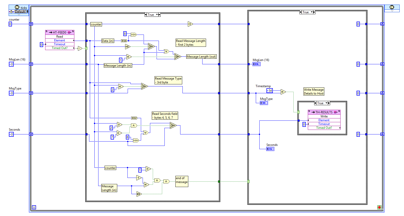
The purple colored box is how the FPGA receives the data from the host. In a live application, the purple colored box, also known as the “Read (FIFO Method)” can have this data come directly from a 10 gigabit connection, or from another loop inside the FPGA.
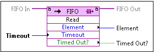
(Read more about this method on National Instruments website: https://zone.ni.com/reference/en-XX/help/371599H-01/lvfpgahost/fpga_method_fifo_read/)
As the data comes in, a counter is started at 0, and depending on the element count, the data is stored in different output variables. The first 2 bytes are the message length, the 3rd is the message type, the 4th, 5th, 6th, and 7th elements are the Seconds portion of the message.
The counter is then compared to the message length variable, and when they are equal, the output variable “Message Done” is set to true. Here is the bottom portion of the screen shot from above:

After the end of the message is read, we have a case structure, which is similar to an if statement but for FPGAs, which will read the appropriate variables and send them back up to the host via a DMA-FIFO. Now this DMA-FIFO can be configured to send data up to the host computer, or to another DMA-FIFO inside the FPGA. For now we are going to send this up to the host for analysis.
Take a look at the right-half of the original FPGA vi screenshot. This element executes once, and reads the Seconds variable and sends it up to the host.
In part 3, I will add another feature – Add Order with MPID, so we can now know in the FPGA when a new order is entered for a particular security, what side that order is on, and how many shares/price. This is more meaningful information that can be used to trade the markets, especially during a Donald Trump speech!