
Source Code:
https://github.com/fpganow/Blink_LEDS
Introduction
There is a saying out there that goes ‘what are you going to do with an FPGA, blink a bunch of LEDs?’
Well… that saying is true. Today I purchased a breakout board for the Zynberry and found an excellent guide on how to do just that:
But I am different and I am going to do more than just ‘blink a bunch of LEDs’. I am going to do something useful. <= It’s a joke… hahaha… Okay, not only am I going to blink a bunch of LEDs by using an FPGA, I am going to do it by using LabVIEW FPGA *and* by having that LabVIEW ‘code’ run on the Zynqberry, all at the same time!
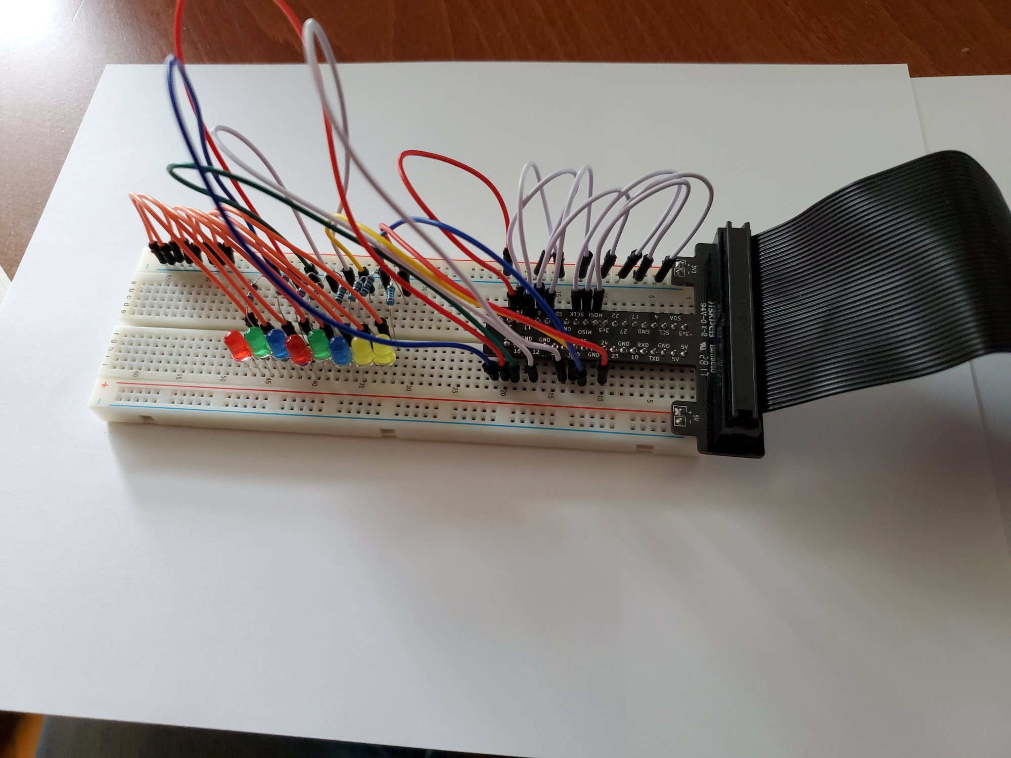
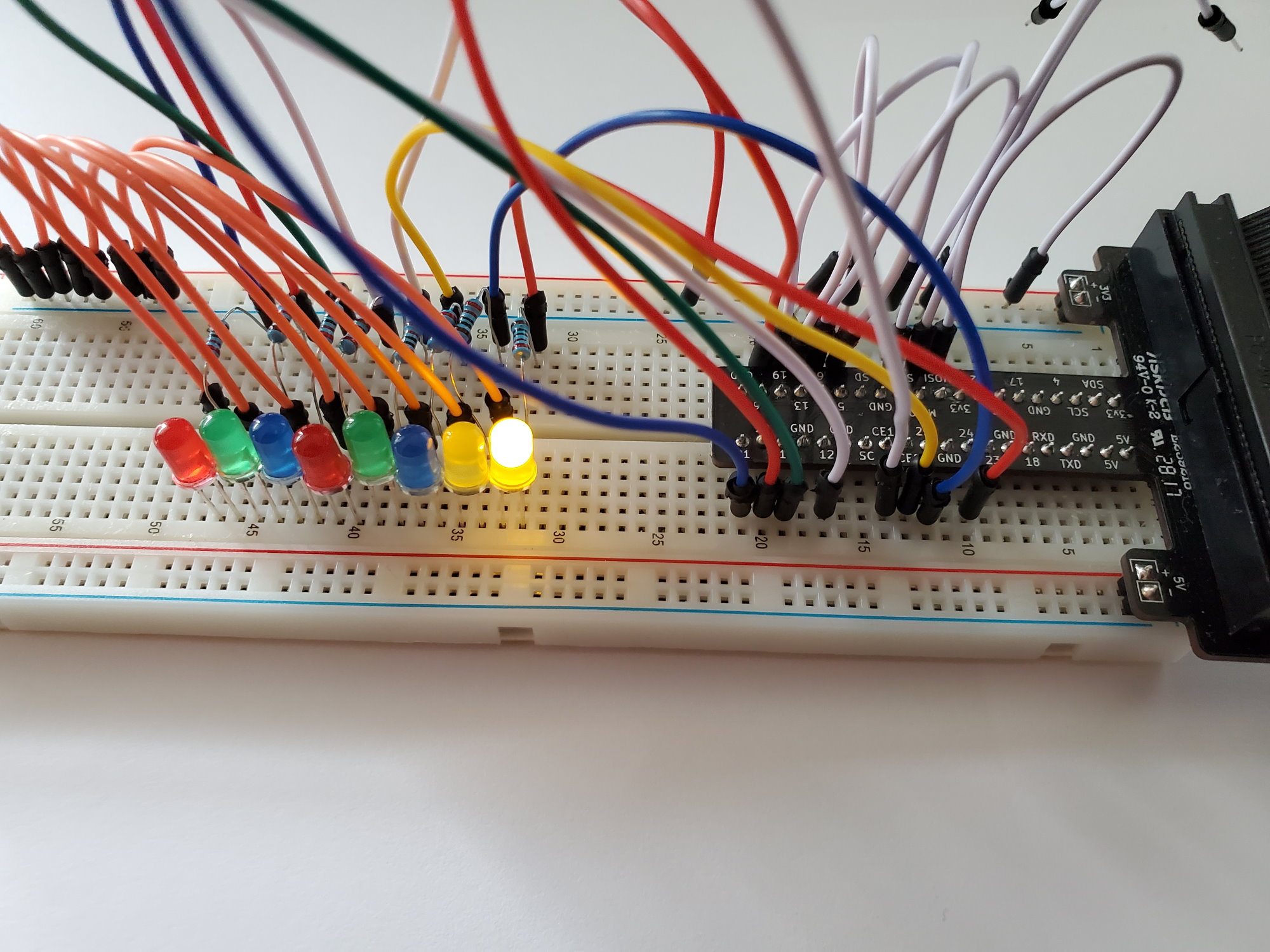
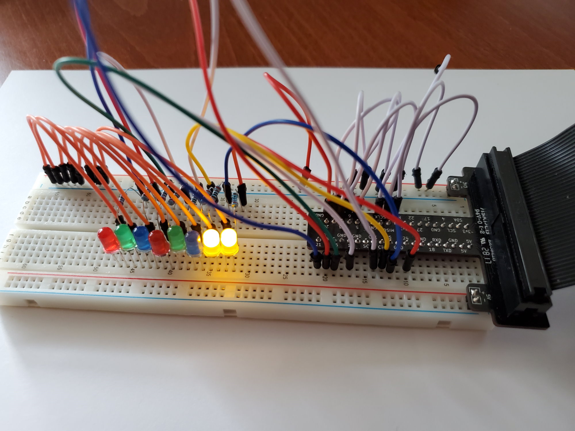
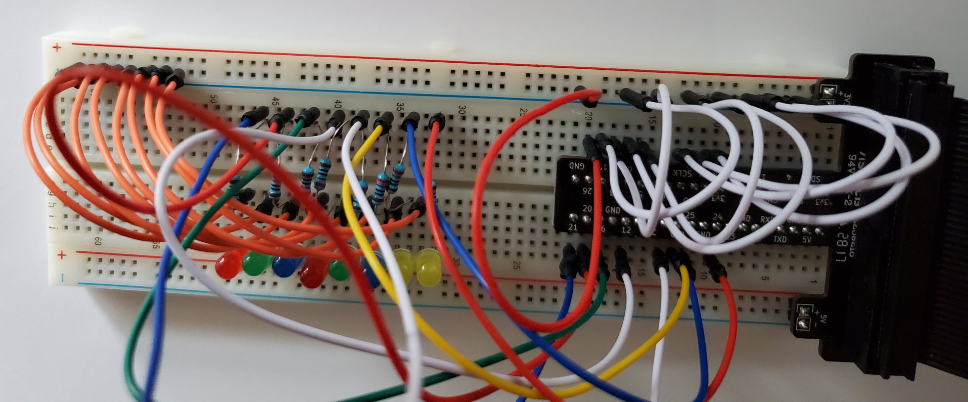
For the first part of this demo, I had to re-learn a bunch of things that I learned in my High School electronics class (thank you Bronx Science – www.bxscience.edu). What did I re-learn? How to power an LED without shorting the thing out… <= that was another joke hahaha. I hope you laughed. Anyway, in the end, I used the breadboard provided by some electronics kit, along with three regular LEDs, one RGB LED, some push buttons and several 220 Ohm resistors. For testing I brought power to this breakout board by using a regular battery pack and the Breadboard 5v/3v Power Supply Kit made by inland. This is not important right now, so I will cover what I did in another post.
<TODO: Insert the link here…>
List of Parts:
I purchased everything from the Flushing Microcenter, which in my opinion has become a very suitable replacement for Radio Shack.
You don’t need to buy exactly what I did, but you will need the following components:
- 2 x LEDS
- 2 x220 Ohm Resistors
- A couple of jumper cables
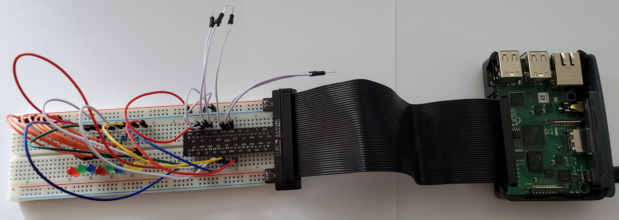
- A Raspberry Pi 2 breakout board
I got these components from the following kits:
- Inland Breadboard 5v/3v Power Supply Kit
- Inland Electronic Parts Pack (KN3B)
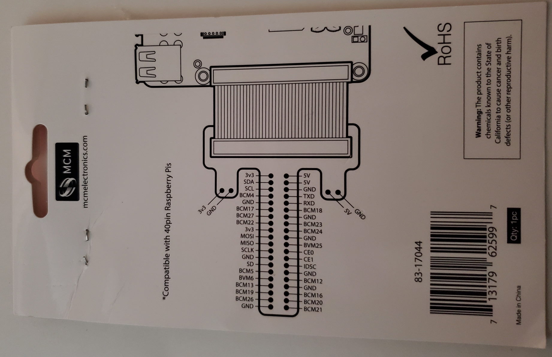
- MCM Electronics 40 Pin GPIO Breakout and Cable for Raspberry Pi
Pictures of the Boxes:
Why pictures? Well, because these parts seem so generic that I can’t even find them online for sale.

Simple Example
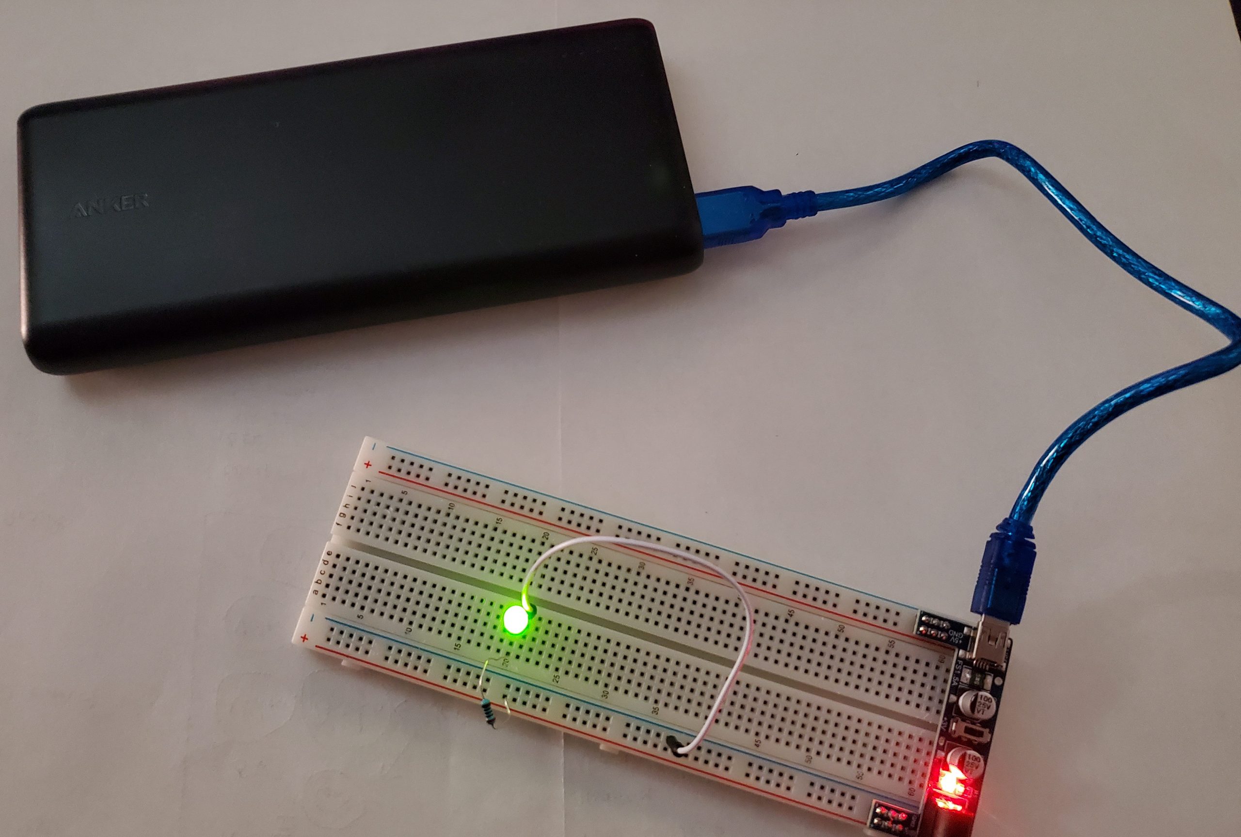
The TL;DR for this one is – Connect the positive pin of the power bank to a 220 Ohm resistor, then the resistor to the positive end of the LED, then the negative end of the LED to ground. Why? Because if you wire an LED directly to the +3.3V you will likely short it out.
The LabVIEW Part
Okay, so now that I gave myself a nice refresher on using electronics, while having fun, which is the most import part I then started to do something similar but with LabVIEW FPGA and the NI LabVIEW FPGA IP Export Utility.
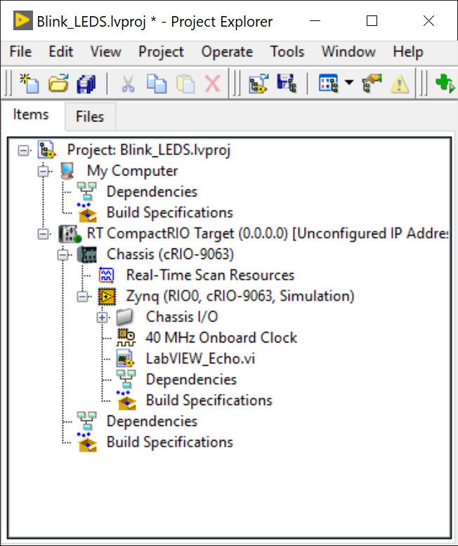
I created a LabVIEW FPGA project using LabVIEW 2020 (32-bit version) and added a target that uses a Zynq family FPGA such as the Real-Time Compact RIO part cRio-9063. The following screenshots should be sufficient if you have some LabVIEW FPGA experience. If you do not, you will need to get some. I would like to provide a more in-depth guide on that at some point.

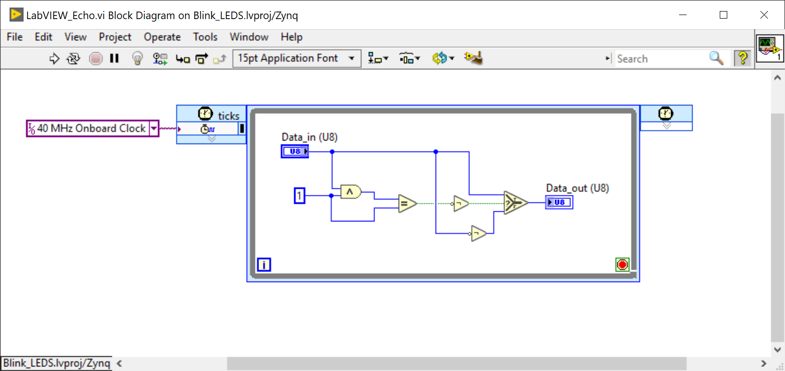

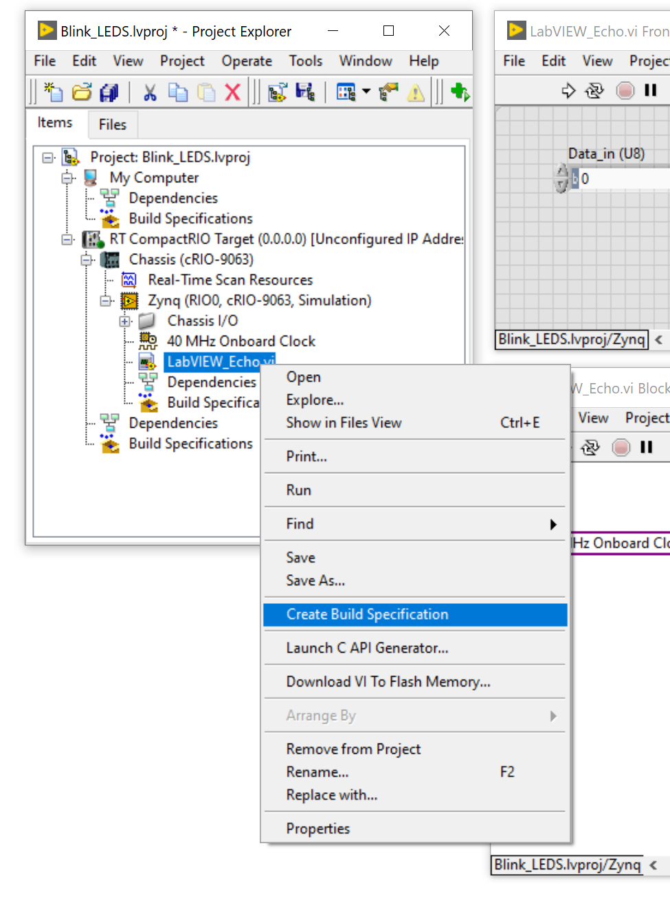
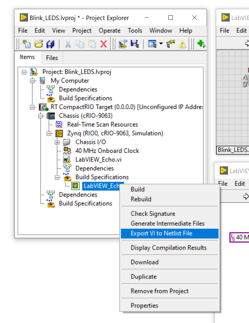
LabVIEW FPGA IP Export Utility Section
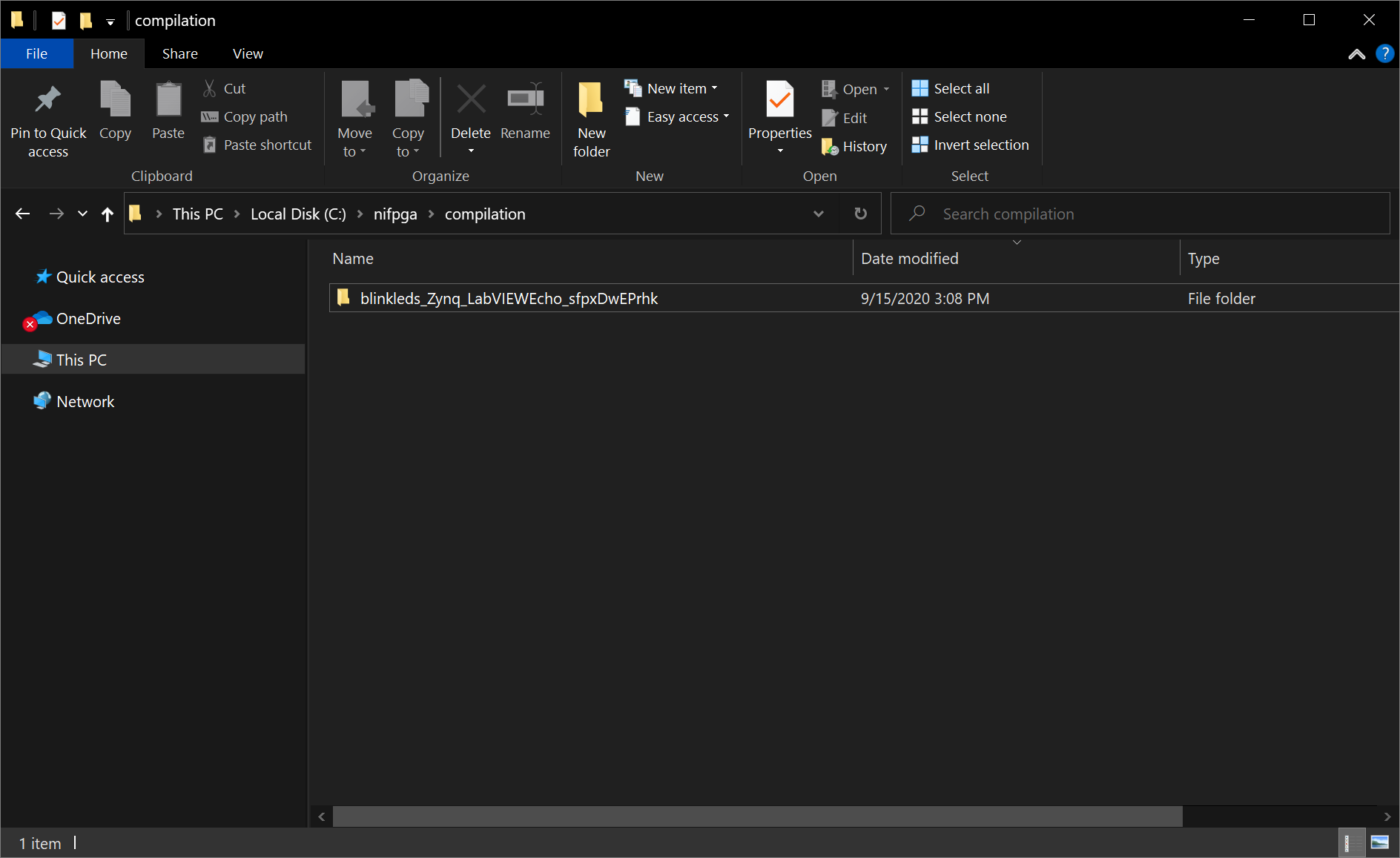
So what does “Export VI to Netlist File” do? It creates two files. A Xilinx dcp file, which I believe stands for “design checkpoint”, and corresponding vhdl wrapper file for it. Now these 2 files have the same name, but with a different extension, cand this file name is like a C++ function that has been mangled. Which means that if you want to keep things simple, just call the VI something simple and short like “adder”, instead of “My NI LabVIEW to FPGA to Vivado Wrapper for blah blah blah”. Anyway, the design above generates two files that get placed in to the C:\NIFPGA\compilation directory. The name of the sub-directory will again follow some sort of name-mangling convention. For me I have:
Vivado Section
Now create a Vivado project and make sure you are using the same version of Vivado as LabVIEW is using. Since I am using LabVIEW 2020, the version of Vivado is 2019. You can use the version that is packaged with LabVIEW, or you can download it yourself. I chose to download it myself so I get whatever NI has decided or had to strip out as part of their agreement to distribute with LabVIEW.
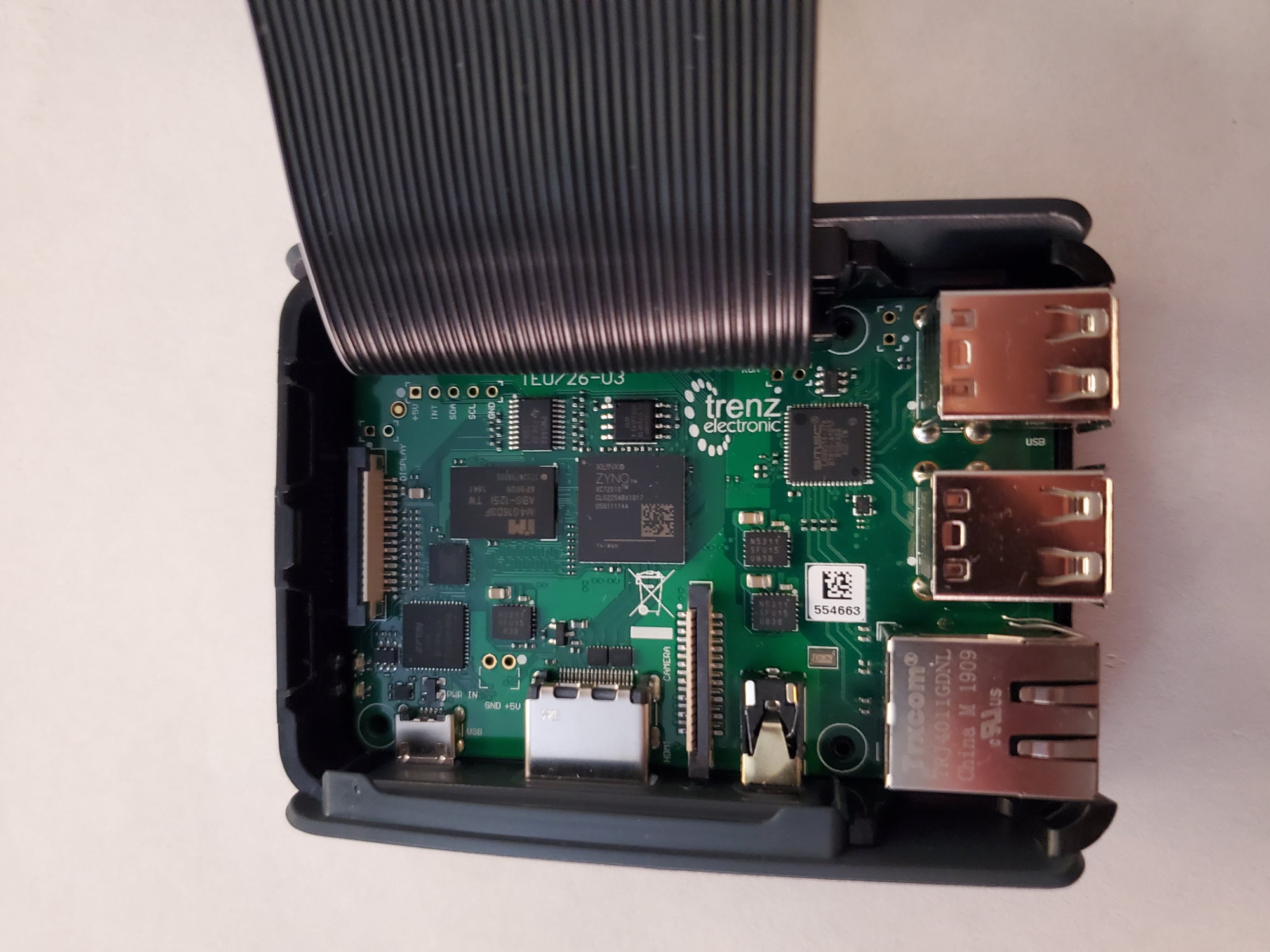
Zynqberry Board Parts
You should install the Zynqberry board parts file.
From the Trenz Electronics homepage for the Zynqberry:
Download one of the Reference Designs for a version of Vivado close to 2019.1
Extract the zip file and look for the board_files directory, and it should contain two directories, in my case it is:
- TE0726
- TE0726_7S
You want to copy these directories to your Vivado installation to the C:\xilinx\Vivado\2019.1\data\boards\board_files directory. My directory looks like this:

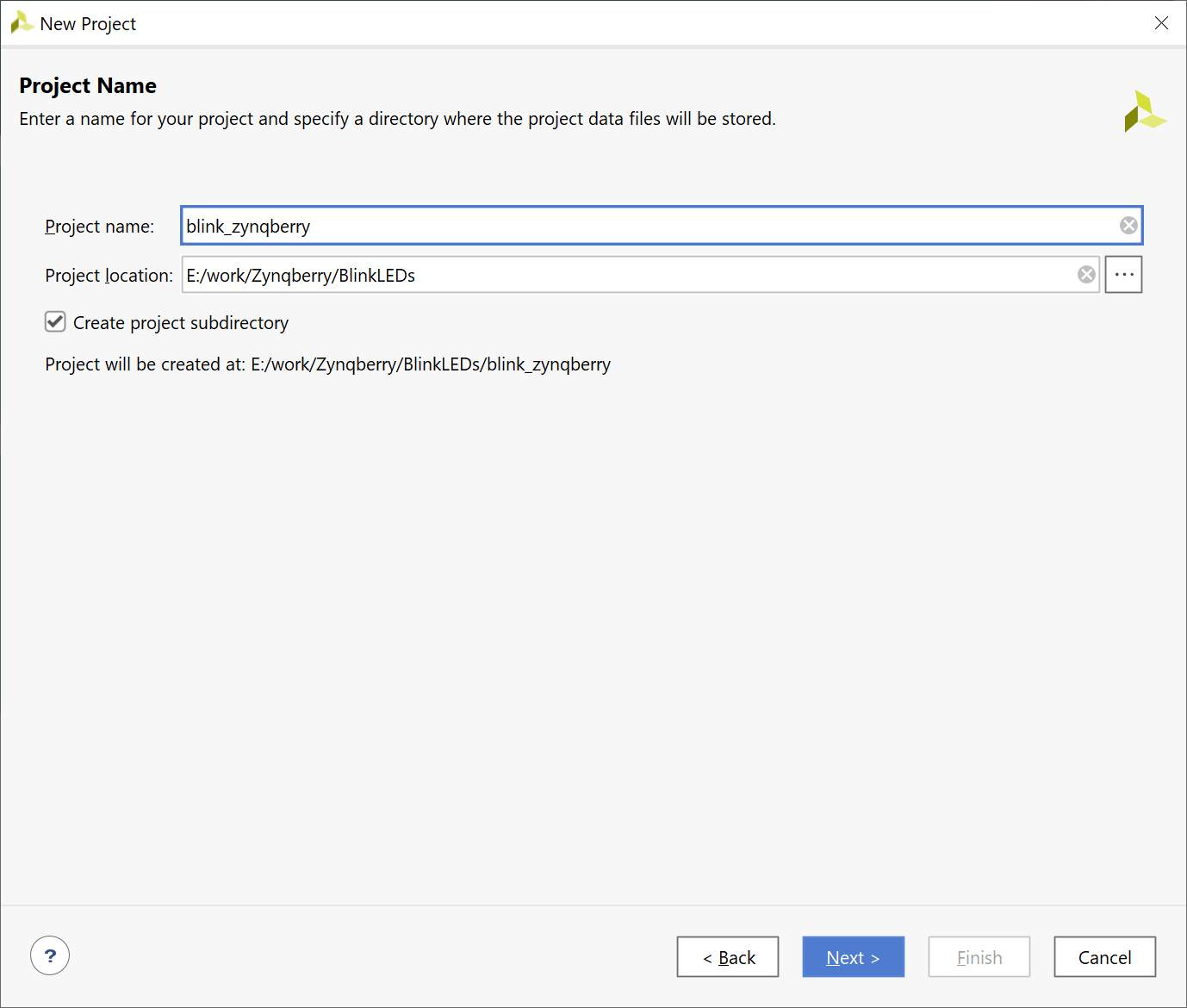
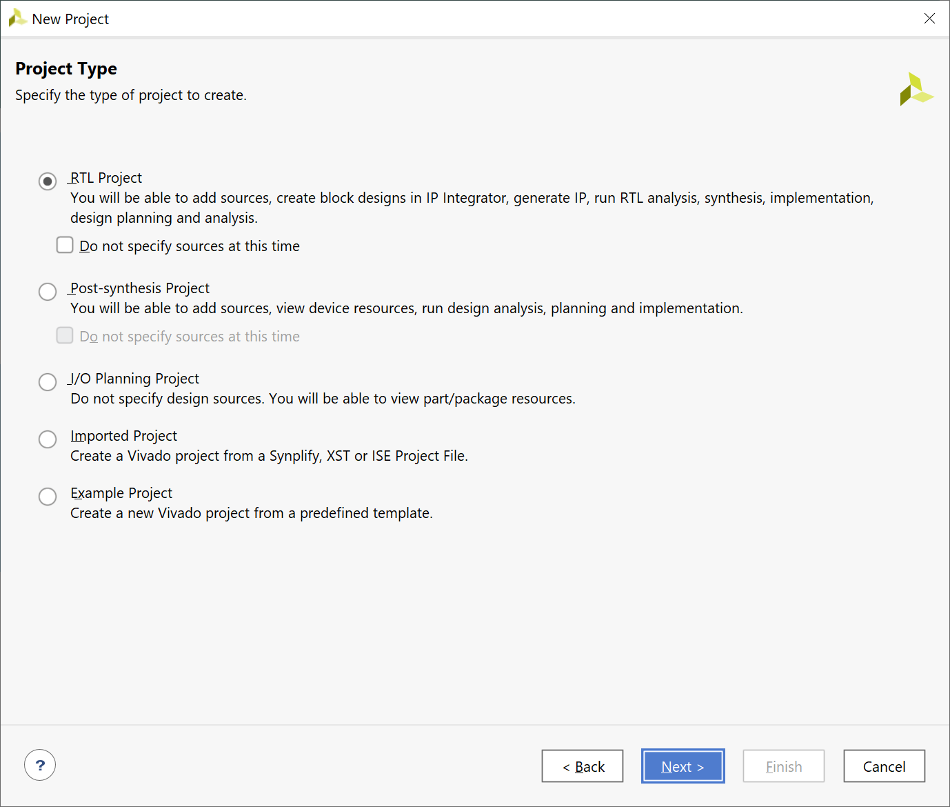
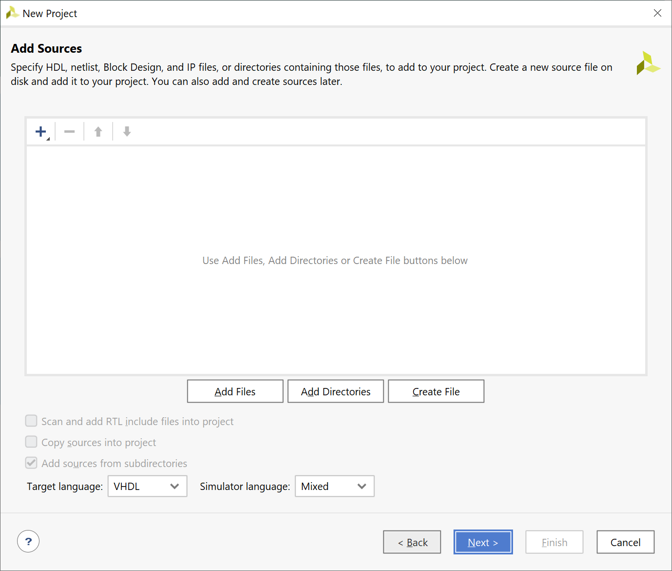
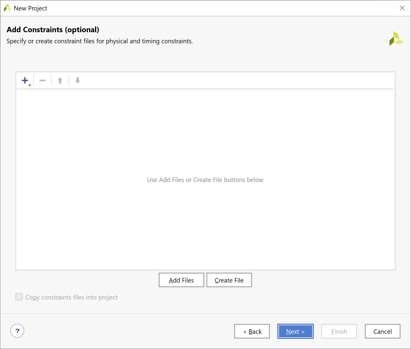
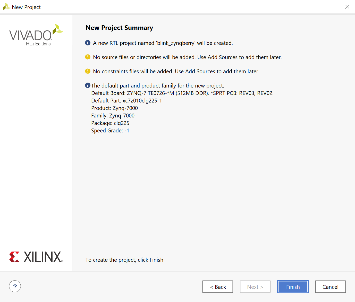
Vivado Create Project
I hope you have some experience using Vivado, if not I will try to include enough information for you. (Please comment below if anything is unclear, just reference the picture # and the title heading)

![]()
Vivado Block Design
I hope you have created a Block Design before. It is cool. It reminds me somewhat of LabVIEW, but coming from a ‘text-based’ programming point of view. Follow these pictures and create a Block Design in your Vivado project which will map to what occurs on the Zynqberry board. To the professional VHDL developers out there, yes, I am aware that I may not need to include the Zynq Processor. I say this only now… as I am writing this post.


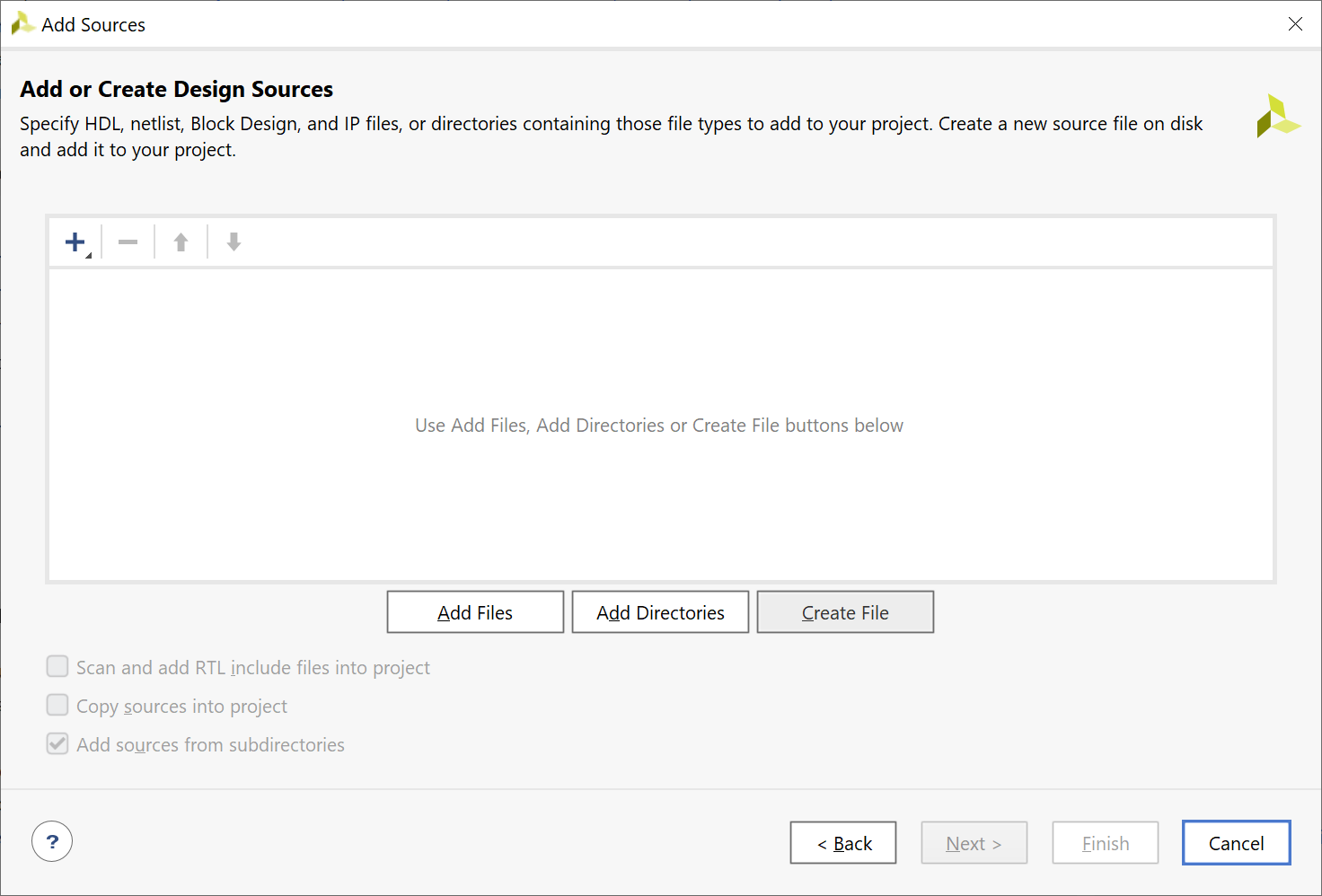
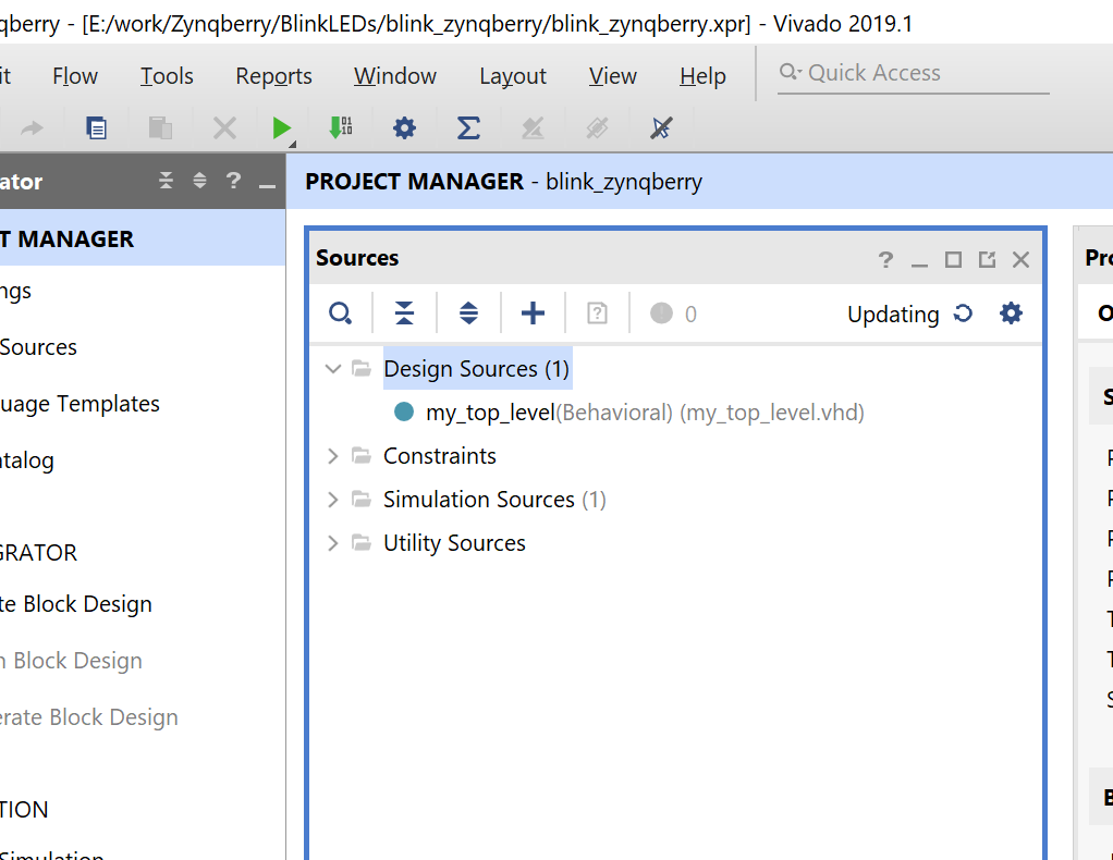
Add the LabVIEW Exported IP
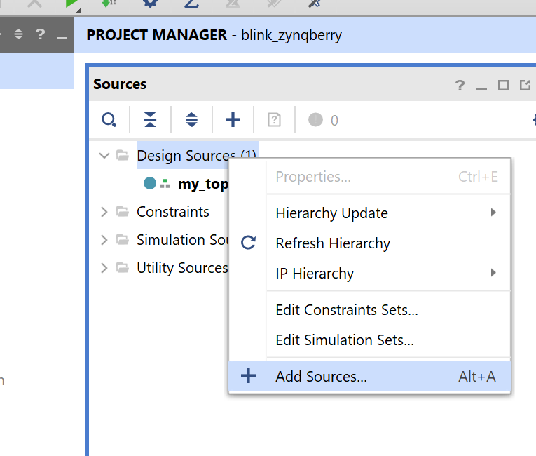
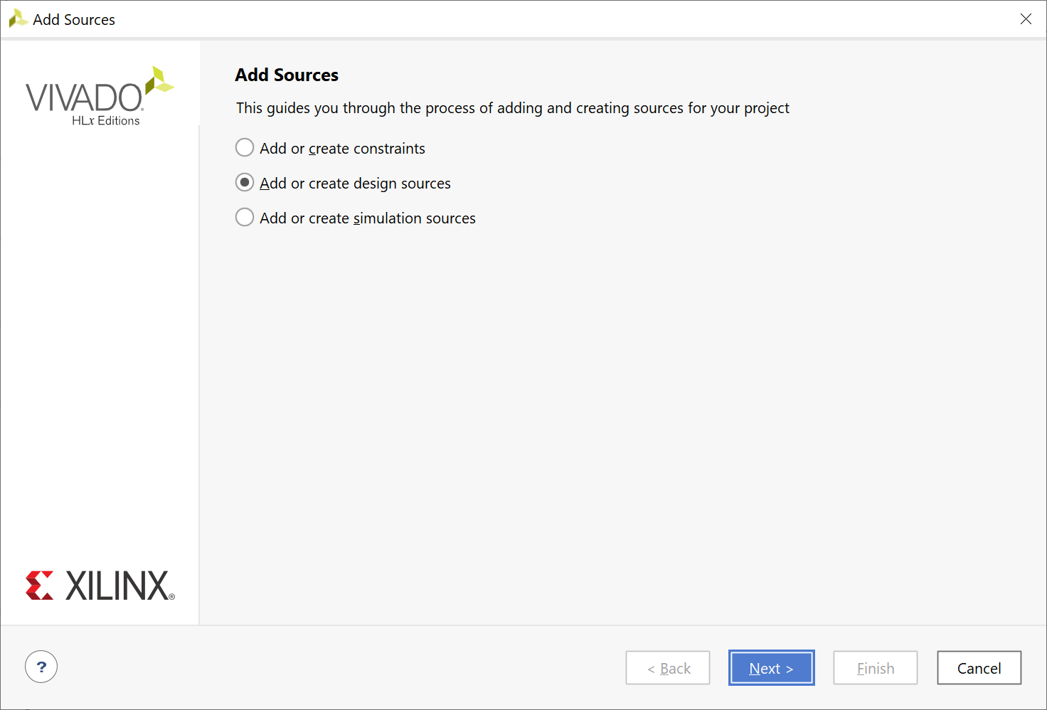
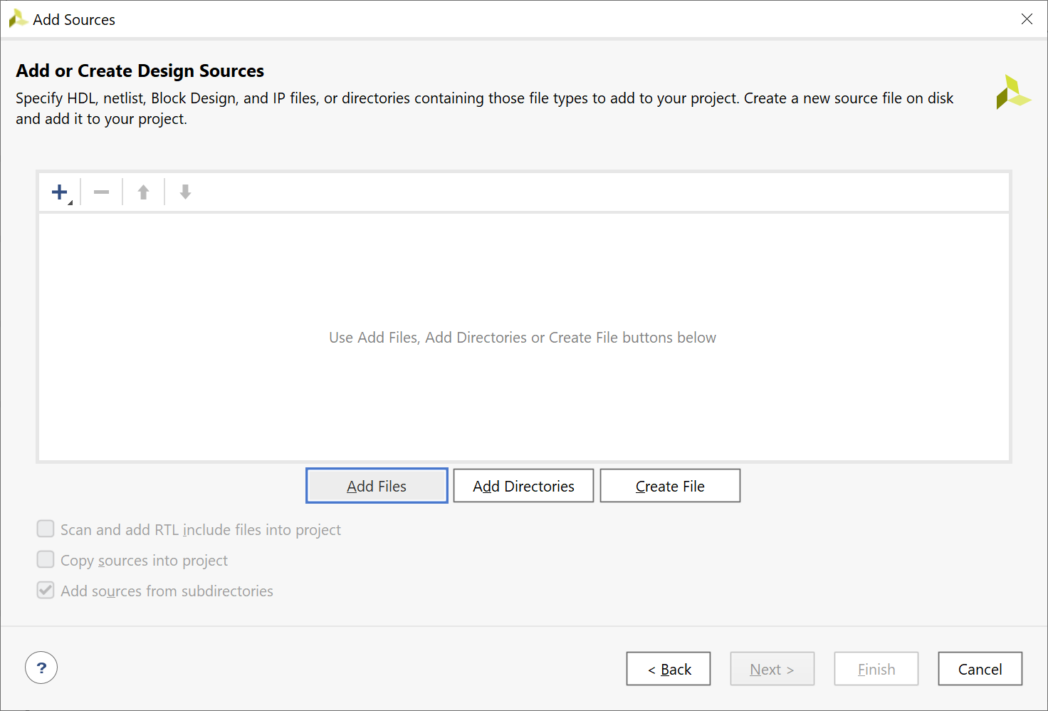

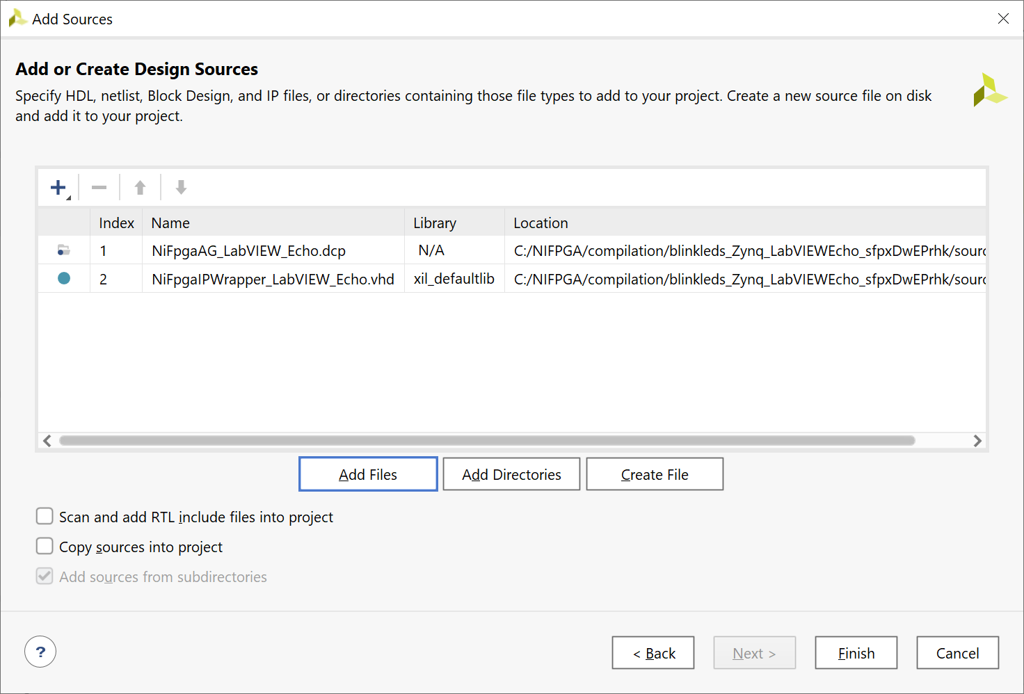
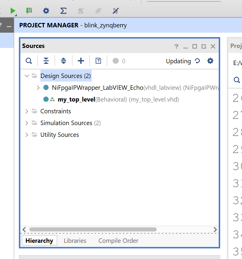
Add the LabVIEW Exported IP to the top-level VHDL Module
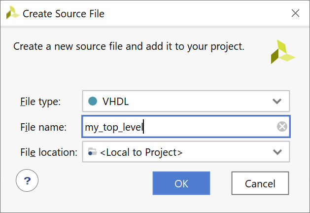
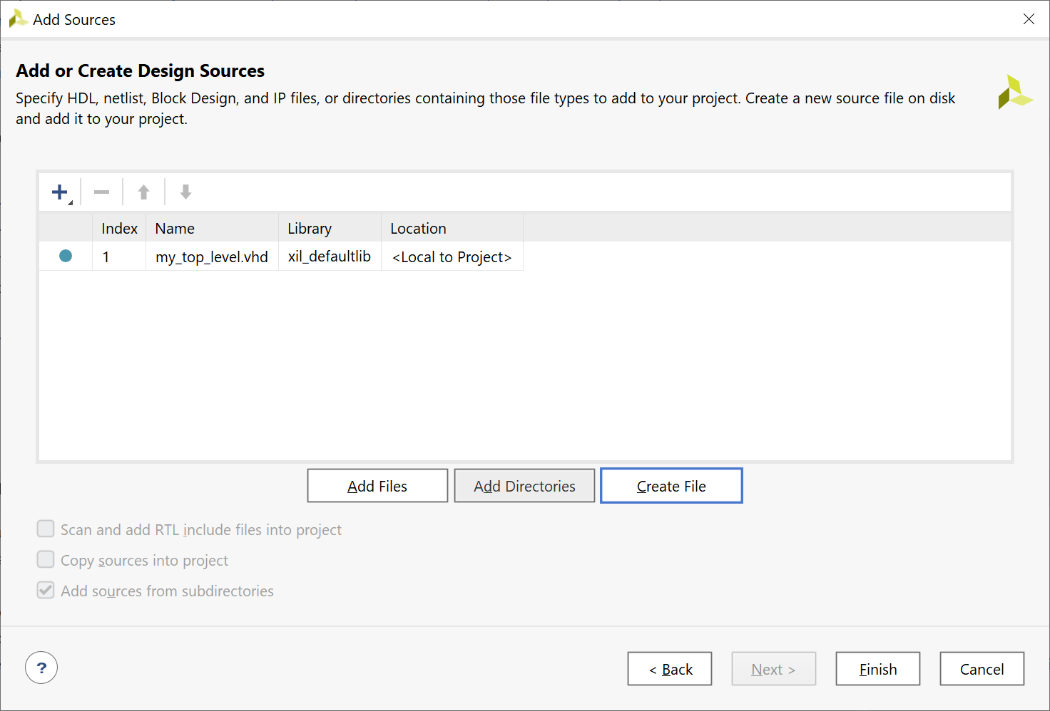
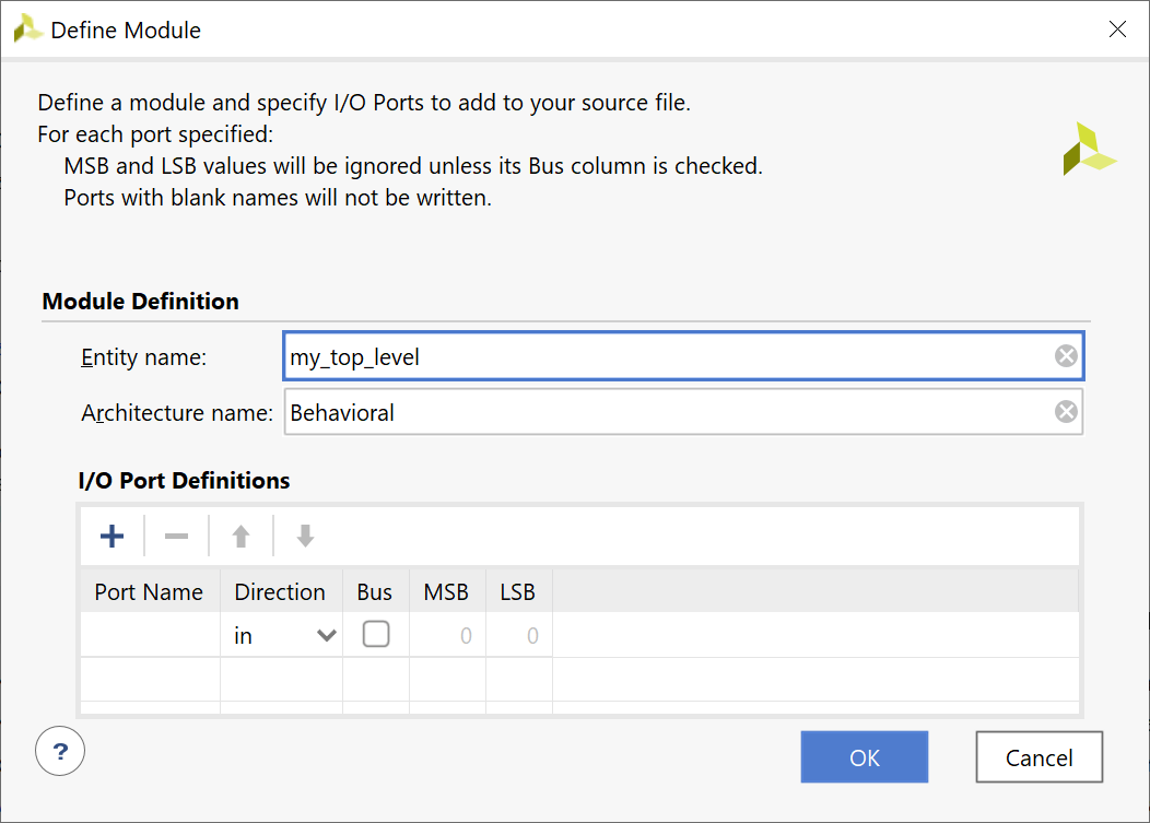
Modify the my_top_level.vhd file to look like this picture:
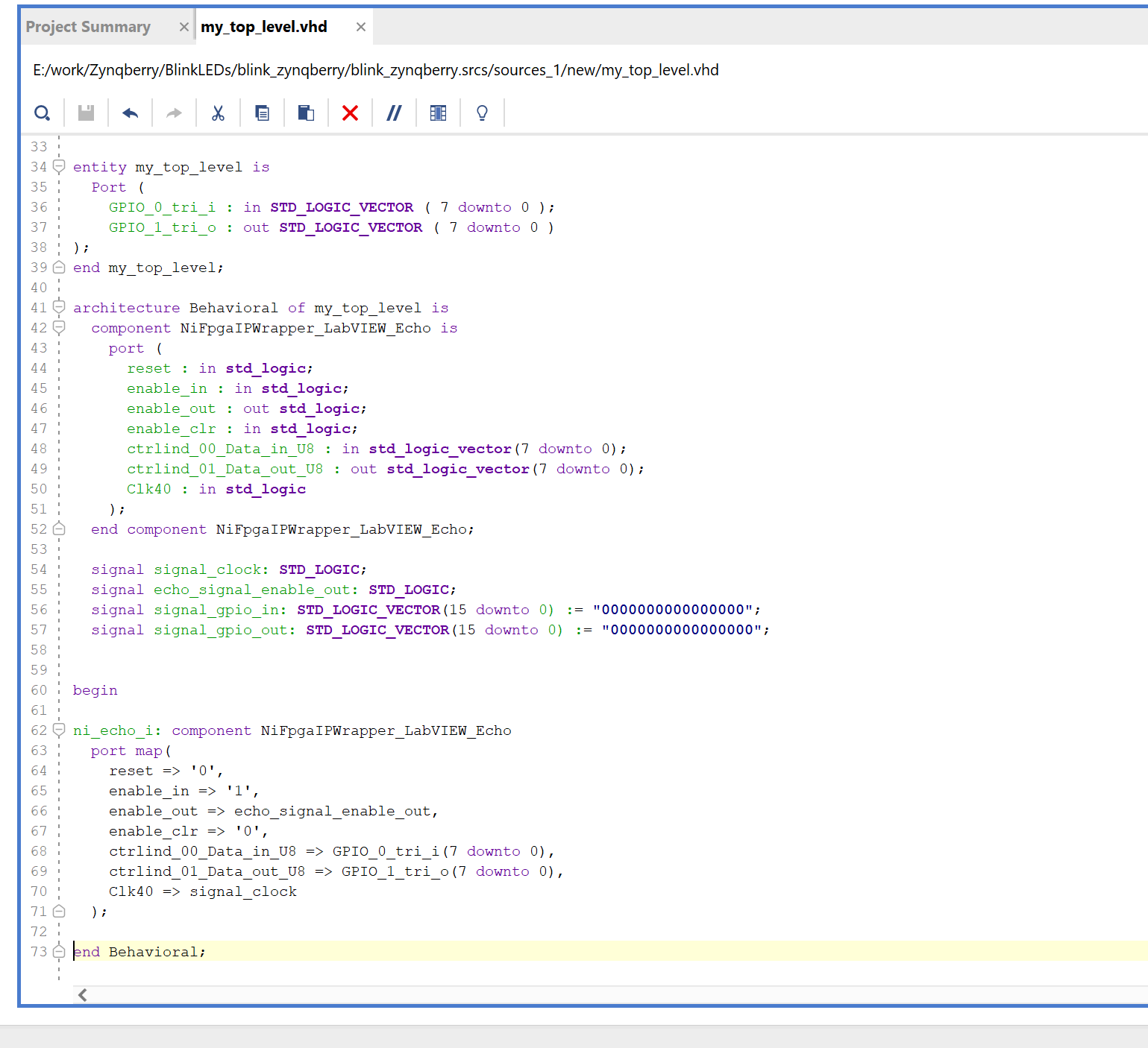
paste the following:
|
library IEEE;
use IEEE.STD_LOGIC_1164.ALL;
— Uncomment the following library declaration if using
— arithmetic functions with Signed or Unsigned values
–use IEEE.NUMERIC_STD.ALL;
— Uncomment the following library declaration if instantiating
— any Xilinx leaf cells in this code.
–library UNISIM;
–use UNISIM.VComponents.all;
entity my_top_level is
Port (
GPIO_0_tri_i : in STD_LOGIC_VECTOR ( 7 downto 0 );
GPIO_1_tri_o : out STD_LOGIC_VECTOR ( 7 downto 0 )
);
end my_top_level;
architecture Behavioral of my_top_level is
component NiFpgaIPWrapper_LabVIEW_Echo is
port (
reset : in std_logic;
enable_in : in std_logic;
enable_out : out std_logic;
enable_clr : in std_logic;
ctrlind_00_Data_in_U8 : in std_logic_vector(7 downto 0);
ctrlind_01_Data_out_U8 : out std_logic_vector(7 downto 0);
Clk40 : in std_logic
);
end component NiFpgaIPWrapper_LabVIEW_Echo;
signal signal_clock: STD_LOGIC;
signal echo_signal_enable_out: STD_LOGIC;
begin
ni_echo_i: component NiFpgaIPWrapper_LabVIEW_Echo
port map(
reset => ‘0’,
enable_in => ‘1’,
enable_out => echo_signal_enable_out,
enable_clr => ‘0’,
— ctrlind_00_Data_in_U8 => “00011100”,
ctrlind_00_Data_in_U8 => GPIO_0_tri_i(7 downto 0),
ctrlind_01_Data_out_U8 => GPIO_1_tri_o(7 downto 0),
Clk40 => signal_clock
);
end Behavioral;
|
Add Master Constraints File
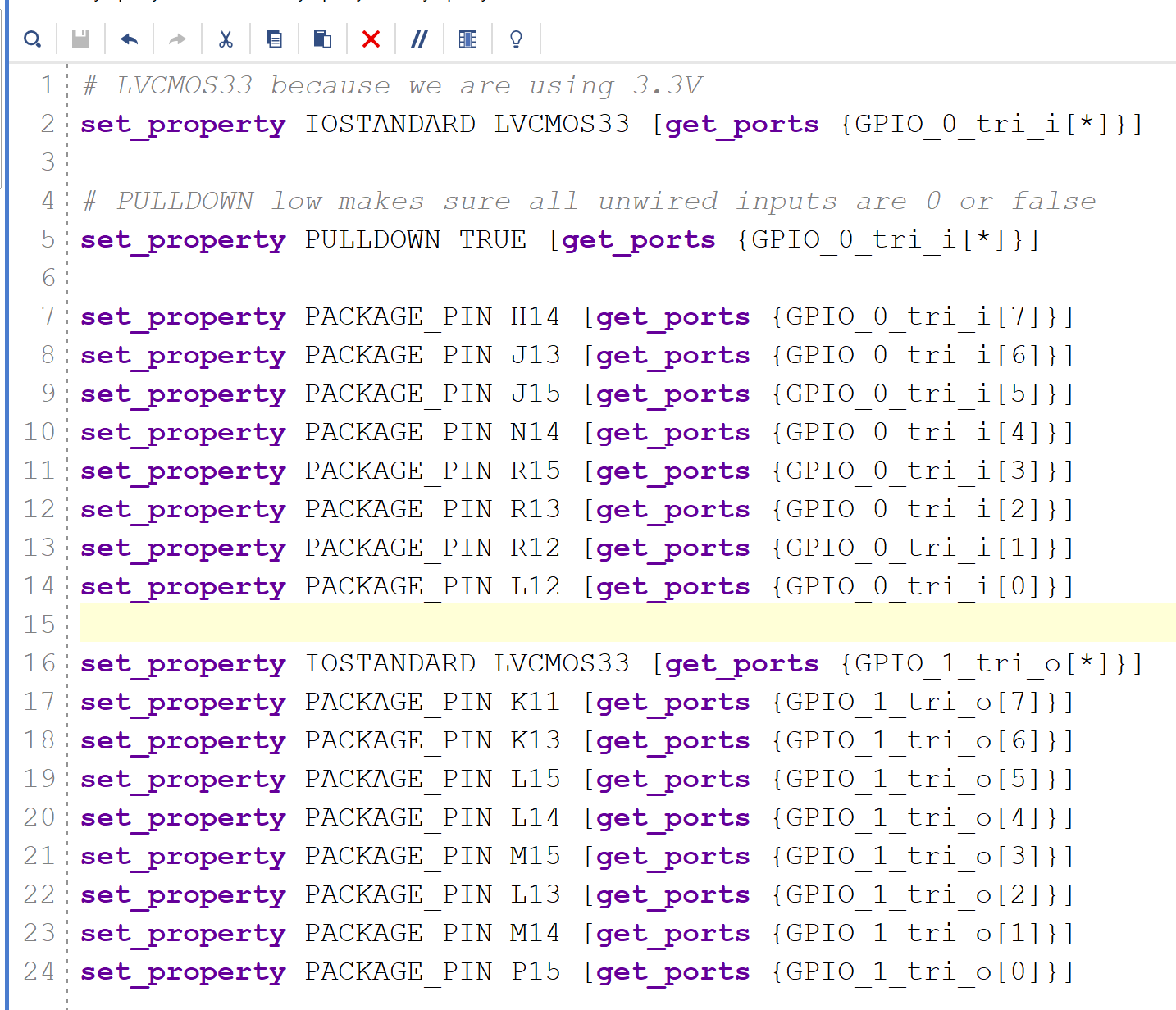
Or cut and paste the following:
|
# LVCMOS33 because we are using 3.3V
set_property IOSTANDARD LVCMOS33 [get_ports {GPIO_0_tri_i[*]}]
# PULLDOWN low makes sure all unwired inputs are 0 or false
set_property PULLDOWN TRUE [get_ports {GPIO_0_tri_i[*]}]
set_property IOSTANDARD LVCMOS33 [get_ports {GPIO_0_tri_i[*]}]
set_property PACKAGE_PIN H14 [get_ports {GPIO_0_tri_i[7]}]
set_property PACKAGE_PIN J13 [get_ports {GPIO_0_tri_i[6]}]
set_property PACKAGE_PIN J15 [get_ports {GPIO_0_tri_i[5]}]
set_property PACKAGE_PIN N14 [get_ports {GPIO_0_tri_i[4]}]
set_property PACKAGE_PIN R15 [get_ports {GPIO_0_tri_i[3]}]
set_property PACKAGE_PIN R13 [get_ports {GPIO_0_tri_i[2]}]
set_property PACKAGE_PIN R12 [get_ports {GPIO_0_tri_i[1]}]
set_property PACKAGE_PIN L12 [get_ports {GPIO_0_tri_i[0]}]
set_property IOSTANDARD LVCMOS33 [get_ports {GPIO_1_tri_o[*]}]
set_property PACKAGE_PIN K11 [get_ports {GPIO_1_tri_o[7]}]
set_property PACKAGE_PIN K13 [get_ports {GPIO_1_tri_o[6]}]
set_property PACKAGE_PIN L15 [get_ports {GPIO_1_tri_o[5]}]
set_property PACKAGE_PIN L14 [get_ports {GPIO_1_tri_o[4]}]
set_property PACKAGE_PIN M15 [get_ports {GPIO_1_tri_o[3]}]
set_property PACKAGE_PIN L13 [get_ports {GPIO_1_tri_o[2]}]
set_property PACKAGE_PIN M14 [get_ports {GPIO_1_tri_o[1]}]
set_property PACKAGE_PIN P15 [get_ports {GPIO_1_tri_o[0]}]
|
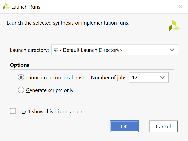
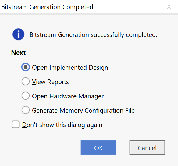
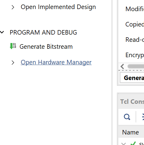
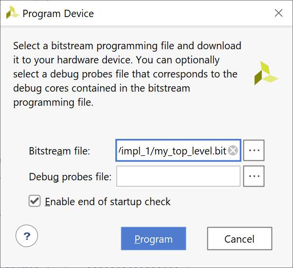
Generate Bitstream


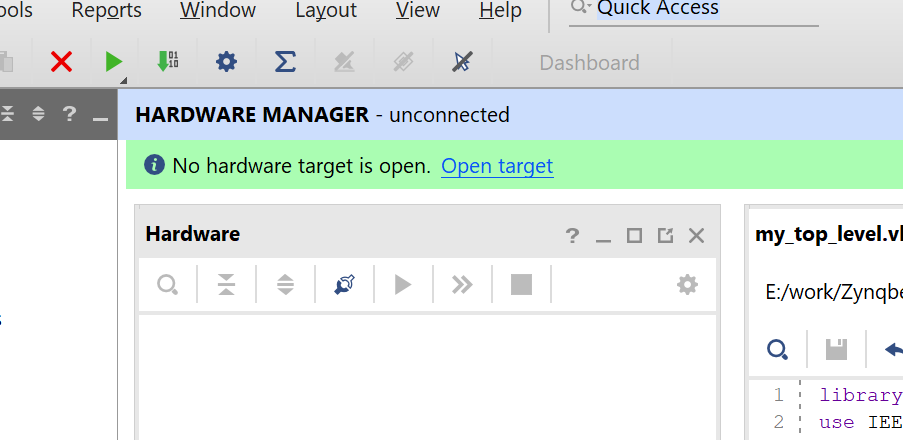
Program and Run!

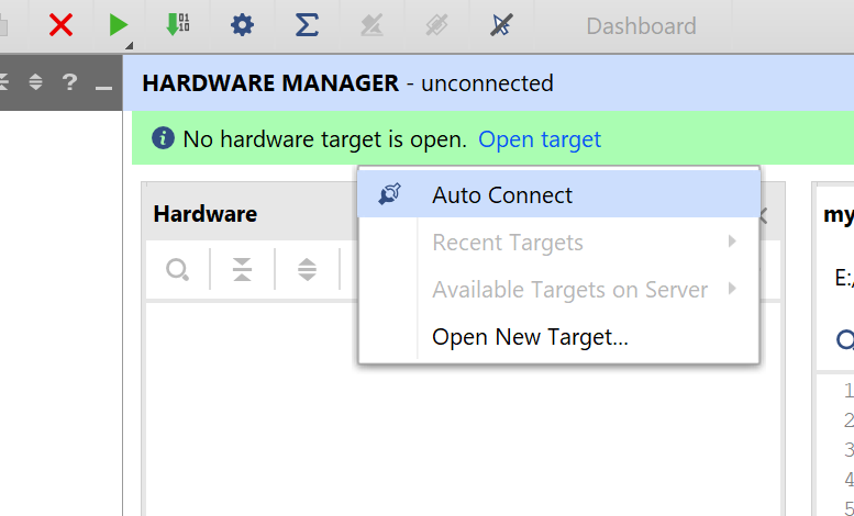


Pictures….
1 thought on “Zynqberry with Breakout Board and LabVIEW”